| C l y d e B u i l t | home |
| Queen mary | RY Britannia | Queen Elizabeth | Queen Elizabeth 2 | Abyssinia | Lusitania | Aquitania | British Queen | St Albans | Pole Star | Portland | Cutty Sark |
| RY Britannia |
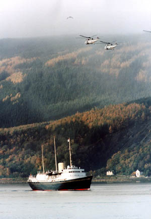
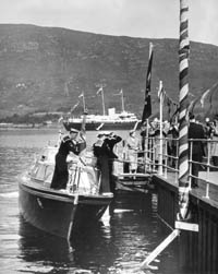
| The Royal Yacht Britannia is one of the world's most famous ships. Launched at John Brown's Shipyard in Clydebank in 1953, the Royal Yacht proudly served Queen and country for forty-four years. During that time Britannia carried The Queen and The Royal Family on 968 official voyages, from the remotest regions of the South Seas to the deepest divides of Antarctica. At the beginning of January 1997, Britannia set sail from Portsmouth to Hong Kong on her last and longest voyage. On 11 December 1997 Britannia was decommissioned at Portsmouth Naval Base in the presence of The Queen, The Duke of Edinburgh and fourteen senior members of The Royal Family. Four months later, after intense competition from cities around the UK, the Government announced that Edinburgh was successful in its bid to become Britannia's new home. She is now owned by The Royal Yacht Britannia Trust, a charitable organisation whose sole remit is the maintenance of Britannia in keeping with her former role. Britannia is now permanently moored in Edinburgh's historic port of Leith and visitors can step on board the ship that was once home to the world's most famous family. The Chairman of The Former Royal Yacht Britannia Trust is The Rt Hon Viscount Younger of Leckie KT KCVO TD DL and his fellow Trustees are The Rt Hon Eric Milligan, Rear Admiral Neil E Rankin CB CBE, Mr Timothy Clifford and Mr Terry Smith. 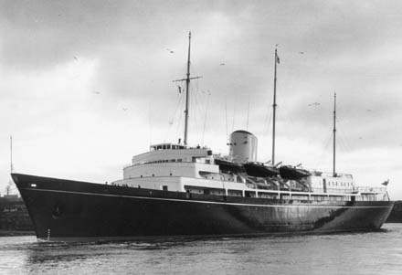 |
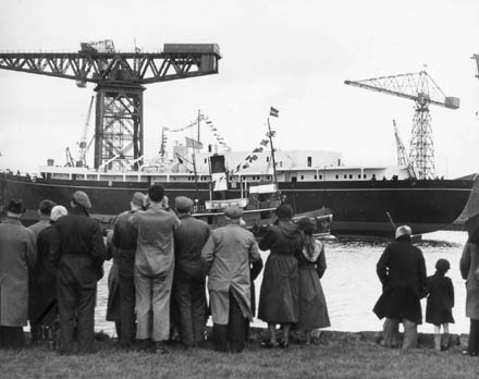
Designer / Builder: Sir Victor Shepheard, Director of Naval Construction; and John Brown & Co. Ltd Launched: 16th April 1953 by HM Queen Elizabeth II
Commissioned: At sea, 11th January 1954
Length overall: 125.65m or 412ft 3in
Length on waterline: 115.82m or 380ft
Length between perpendiculars: 109.73m or 360ft
Maximum breadth moulded: 16.76m or 55ft
Breadth at upper deck moulded: 16.61m or 54ft 6in
Depth moulded to upper deck: 45ft abaft midships: 9.90m or 32ft 6in
Depth moulded to upper deck at fore perpendicular: 12.29m or 40ft 4in
Depth moulded to upper deck at after perpendicular: 10.31m or 33ft 10in
Load displacement: 4,715 tons
Mean draft at load displacement: 5.2m or 15ft 7in
Gross tonnage: 5,862 tons
Shaft horsepower: 12,000
Speed: 22.5 knots maximum 21 knots continuous
Engines: Two geared steam turbines, developing a total of 12,000 shaft horse power. Two main boilers, and an auxiliary boiler for harbour requirements by Foster Wheeler
Range: 2,196 miles at 20 knots (burning diesel fuel)
2,553 miles at 18 knots (burning diesel fuel)
Main Mast Height: 42.44m or 139ft 3in - Royal Standard
Fore Mast Height: 40.54m or 133ft - Lord Admiral's Flag
Mizzen Mast Height: 36.22m or 118ft 10in - Union Flag
Fuel & Water: 330 tons of fuel oil providing a range of 2,000 miles at 20 knots. 120 tons of fresh water. Additional tanks can increase fuel capacity to 490 tons and fresh water capacity to 195
tons
Propeller Diameter: 3.12m or 10ft 3ins
Pitch: 2.74m or 9ft Developed blade area: 5.17m2 or 55.7ft2
Tip clearance from hull: 0.84m or 2ft 9in
Maximum rudder torque: 125 tons ft at 14 knots astern and 30.5° angle
Rudder Torque at 22 knots: 69 tons ft at 35° angle
Rudder Torque at 15 knots: 33 tons ft at 35° angle
Maximum normal rudder force: 63.5 tons at 22 knots ahead, and 25.5 tons at 14 knots astern
In the load condition the ship carries 330 tons of oil fuel which is more than sufficient to obtain the design endurance of 2,000 miles at 20 knots, and 120 tons of fresh water which is considered sufficient for two days’ supply without evaporators working.
Extra tank capacity is available for use on long ocean passages, and by its use the oil fuel capacity can be increased to 490 tons and the fresh water to 195 tons. These additional tanks will normally remain empty.
Design
In 1938, the Admiralty considered the possibility of building a ship which would not only replace the Royal Yacht Victoria and Albert, then nearly 40 years old, but which could be economically converted to a hospital ship in the event of a war. Outline drawings and a statement of essential requirements were accordingly prepared, and in 1939 these were sent to some of the principal shipbuilders in the country, inviting them to submit more detailed proposals. With the advent of war, however, the matter was dropped.
In 1951 the project was revived, and in October of that year the Admiralty announced that a medium-sized hospital ship would be put into the re-armament programme and would be used in peacetime to replace H.M. Yacht Victoria and Albert, which by then was not seaworthy. Sketch designs were started in the Admiralty on the basis of the 1939 design reduced in size.
Although the title of this paper is "Her Majesty’s Yacht Britannia," most of the subject matter refers equally to the hospital ship role.
It was decided that the ship should be suitable for service in both tropical and arctic waters. A continuous seagoing speed of 21 knots was required, and this meant that a trial speed of 22 knots with the ship in the load condition, with clean bottom and in temperate waters, had to be guaranteed. The endurance required was at least 2,000 miles at 20 knots at load displacement with clean bottom and in temperate waters, allowance being made for the maximum load required for auxiliary machinery and for domestic services.
The necessity for economy in the cost of construction was kept continually in mind during the design and construction of the ship. The late King and subsequently Her Majesty The Queen both stressed this need for economy and made many suggestions with the object of reducing expenditure. Even after the design has been commenced the original requirements were reviewed and many changes were made in order to reduce the size of the ship. It was necessary, however, to ensure that the size of the ship was not so reduced as to impair her seaworthiness when undertaking long ocean passages. Moreover the ship had to be large enough to permit of economical employment as a hospital ship in wartime. After much consideration it was decided that the smallest ship to meet these requirements was one of about 4,000 tons displacement, and every effort was made to produce an acceptable design with a displacement as near to this figure as practicable.
It will be appreciated that the design of a dual-purpose ship such as this, is far from being straightforward. Designs had to be developed simultaneously for the Royal Yacht and hospital ship roles and the best arrangement worked out which would meet both requirements and at the same time ensure that the work and cost of conversion in wartime would be kept to a minimum. For example, certain features have been embodied in the design which add to the value of the ship as a Royal Yacht, but which are not altogether essential for that purpose. They would however be necessary if and when the ship is used as a hospital ship. Such features include ship’s stabilizers, certain air-conditioning, large laundry facilities and comparatively high speed, none of which could be added on conversion as a hospital ship except at considerable additional expense and long delay in completion.
As a Royal Yacht the ship will wear the white ensign and be manned by a naval crew. As a hospital ship she would be manned by a merchant service crew and wear the red ensign.
The design was developed, and statements of requirements were prepared at the Admiralty, by the end of 1951. These were approved by His late Majesty. Later the plans and a model of the ship were submitted to and approved by Her Majesty The Queen.
Britannia has been given a modern appearance with clipper bow and modified cruiser stern. This was preferred to the more traditional swan bow and counter stern previously associated with Royal Yachts – in fact, it was the wish of King George VI that the new yacht should be on modern lines, but not too modern. Three masts are a requirement for a Royal Yacht; the Royal Standard is worn at the Main, the Flag of the Lord High Admiral at the Fore, and the Union Flag at the Mizzen. A single funnel is in keeping with a well-balanced profile.
From the outset it was obvious that the Royal and State apartments and accommodation for the Household and Royal staff should be aft, with the ship’s company accommodated forward. This has led to the after super-structure being slightly larger than one would have desired from a purely aesthetic point of view, but nevertheless it is considered that a well balanced, graceful and dignified appearance, in keeping with the ship’s function, has been achieved.
One of the most important factors when placing the contract for the construction of Britannia was the requirement that the vessel should be completed by the end of 1953 or by early Spring 1954 at the latest. This was by no means an easy requirement to meet under the difficult conditions then prevailing in the shipbuilding industry. Apart from the shortages of shipbuilding materials and equipment generally, the heavy drawing office load required for a ship of this type presented a special problem.
Preliminary enquiries for the construction of the ship were made from seven firms, and from the replies received it was clear that Messrs. John Brown & Co. (Clydebank) Ltd. offered the best prospect of meeting the requirements.
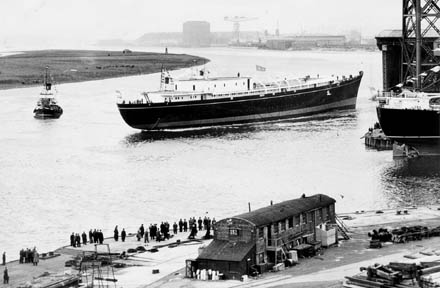
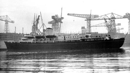
The order was accordingly officially placed with that firm in February 1952. The keel was laid on June 16, 1952, the vessel was launched on April 16, 1953 and was completed and accepted by the Admiralty on January 11, 1954.
Ship Model Experiments
At an early stage arrangements were made for investigations and model experiments to determine the best form of hull to meet the requirements both in calm waters and rough seas. Calculations and experiments were also made to determine the most suitable design of propeller having regard to propulsive efficiency and the avoidance of cavitation, erosion, and vibration. Wind tunnel tests were carried out to ensure that the bridges would be as free from draughts as possible, and to obtain a satisfactory design of funnel. These wind tunnel tests were conducted by the Aerodynamics Division of the N.P.L., Teddington, and are described later in the paper.
The first experiments to determine the resistance of the hull were carried out by Messrs. John Brown, who ran a model in their tank at Clydebank at a displacement corresponding to 4,470 tons, level trim, over a speed range from 14 to 22 knots. Afterwards A.E.W. Haslar ran a model to slightly different displacement and draught and compared the results with those of other good hulls of about the same proportions and speed, including methodical series results. They confirmed that the hull lines were of a very good standard throughout the speed range. Messrs. John Brown then proposed a semi-bulbous bow as showing an improvement in performance above 18 knots although performance was slightly prejudiced below that speed.
The form was modified to include a semi-bulbous bow; the lines were slightly fined forward and filled out aft, and all cut-up forward was deleted. The final model was run by Messrs. John brown with satisfactory results.
Propellers
One of the essential requirements was that the ship should be as free from vibration as possible. Before deciding on the propeller design therefore, calculations were made at A.E.W. Haslar of the natural frequency of vertical flexural vibration of the hull for guidance in determining the number of blades to avoid propeller excitation. The method of basic functions was followed and allowance was made for the influence of entrained water, shear deflection and rotary inertia. Some notes on this method and the assumptions involved are given in Appenidix I. Calculations covered the first nine nodes and the predicted frequencies ranged from 116 cycles per minute for two node vibration to 708 cycles per minute for nine nodes. Higher nodes were not investigated as it was considered that such vibration would be of very small amplitude and not sufficiently stable to be excited by the propellers to any sensible extent.
It may be mentioned that the method followed is comparatively new. It is intricate and fairly lengthy but it is regarded as such a promising advance on previous approaches as to justify the work involved. Naturally, until experience is available as to the validity of the assumptions, including hull stiffness, the calculations can only be regarded as approximate, particularly having regard to the close precision necessary for resonance predictions. However, we were fortified in that a similar approach for a ship of comparable size indicated that the method was trustworthy to cover the range of interest for Britannia.
Allowing a margin on the estimates, it was deduced that three-bladed propellers might stimulate resonance due to shaft excitation superposed on blade excitation over a speed range of 16 ½ to 19 knots. Resonance due to shaft excitation with four-bladed propellers might be excited from 16 to 18 knots and with blade excitation from 14 to 15 knots. Experience on comparable ships suggested that transverse hull vibration might also be excited over the speed range quoted above for three-bladed propellers but only at lower speeds for four-bladed propellers. Resonant vibration might also be excited at lower speeds than mentioned, but experience confirmed that this would be slight and unobjectionable. This vibration might be expected at lower speeds with four-bladed propellers than with three-bladed propellers. On the whole the risk of objectionable vibration was regarded as slight with four-bladed propellers, whereas objectionable vibration might be induced with three-bladed propellers due to a combination of nodes and frequencies.
It was therefore decided to fit four-bladed propellers rather than three-bladed. A loss of speed of the order of one-eight knot was estimated, but this was regarded as acceptable in view of the importance of suppressing vibration. Furthermore, the shipbuilders were confident that the contract condition of a guaranteed trial speed of 22 knots would be met.
Advance calculations indicated that the critical speeds of axial shaft vibration both for three-bladed and four-bladed propellers were greater than the maximum shaft revolutions per minute. The margin for four-bladed propellers was rather small but this was regarded as less serious than the risk of general hull vibration if three-bladed propellers were fitted. A.E.W. Haslar worked out proposed particulars for a four-bladed propeller and Messrs. John Brown prepared the detailed propeller design with the following characteristics:
Diameter 10.25ft.
Pitch 9 ft.
Developed blade area 55.7 sq. ft.
With this diameter propeller a good tip clearance of 2 ft. 9 in. from the hull was obtained.
A model propeller of 12 in. diameter, made in manganese bronze to the usual close tolerances, was tested in the tunnel at A.E.W. Haslar over a range of cavitation number from 6.55 to 1.7 corresponding to a range of nominal ship speed from 13.4 to 26.3 knots. The results are shown in the usual coefficient form in Fig. 3. Photographs of cavitation are shown in Fig. 4. The propulsion curves present the usual characteristics and call for no particular comment except that the propulsive efficiency is favourable for the conditions of revolutions, speed and wake. Cavitation was light and restricted to a small zone of sheet cavitation on the back of each blade towards the tip, and slight face cavitation near the leading edge in the region of 0.5 to 0.8 radius. The latter was avoided by slight washback and this modification was arranged on the spare set of propellers for the ship.
Further remarks on propellers are given under the section on sea trials
Rudder
Very careful consideration was given to the turning qualities of the design and the good results obtained will be appreciated from the section dealing with sea trials. Torque and normal force on the rudder were, however, determined from measurements on a propelled model hull when on a straight course with rudder adjusted in turn to various angles. Results are shown in Figs. 5 and 6.
Maximum rudder torque was estimated to be 125 tons ft. at 14 knots astern and 30 ½ deg. angle. The torque was reduced to 116 tons ft. at 35 deg. angle, but was larger at greater angles outside the operating range. When proceeding at 22 knots ahead the torque was 69 tons ft. and at 15 knots was 33 tons ft., both at full rudder angle of 35 deg.
Maximum normal rudder force was estimated to be 63.5 tons at 22 knots ahead, and 25.5 tons at 14 knots astern.
The centre of pressure was abaft the rudder axis at all forward speeds and for all rudder angles tested. It was not possible however to bring the centre of pressure further forward without unacceptable modification to the stern form.
The results indicated a comparatively small discontinuity in the progressive increase of torque and force with angle in ahead motion at about 30 to 35 deg. and a definite stalling at 30 ½ deg. in astern motion. Geometrically the rudder enters the propeller race at about 30 ½ deg. and the discontinuity may be due to the influence of the propeller race associated in astern motion with the usual stalling phenomena which depend, amount other factors, on aspect ratio.
Generally the results were reasonably consistent with those obtained from tests on other models. The normal force coefficient at 22 knots ahead and 35 deg. angle was 0.026 which compares with a general average value of 0.03 for ships generally, subject to a margin of 10 per cent or so up and down. (Normal force coefficient is P/AV2O, where P = force in lb., A = rudder area in sq. ft., V = speed of ship in ft./sec., O is the rudder angle in degrees.) The torque was consistent with estimates by the strip method.
Seaworthiness
Comprehensive experiments were carried out at A.E.W. Haslar to investigate the sea keeping qualities of the ship. A dynamic model to a scale of 1/32nd full size was tested head-on to uniform waves when towed at speeds corresponding to 10, 15, and 20 knots and in following waves at speeds corresponding to 10 and 20 knots. Tests were also made with the model hove-to head on to the waves. The wave lengths ranged from 200 to 700 ft. at full scale with heights 1/20th and 1/40th the length.
The motion in ahead seas was heavy in long waves, but was reduced in short waves, the motion being small when the length of the wave was less than about three-quarters the length of the ship. Generally, peak oscillations occurred in waves about 30 per cent or so longer than the ship and were more severe at high speed. As an indication of the severity of the extreme motions it may be mentioned that the maximum amplitude of pitch was about 20 deg. (out to out) and of heave 32 ft. (out to out) when the ship was proceeding at 20 knots in waves about 500 ft. long. Whilst it would be unseamanlike, even if practicable, to proceed at this high speed in such heavy seas, it is of interest that the motion is still severe when the ship is hove to.
A considerable increase in hull resistance occurs in waves, which shows the variation in ehp with wave length for various wave heights at a speed of 10 knots. A point of interest is that over the speed range up to 20 knots it was found that the peak of hull resistance occurs in waves which are shorter than those causing peak motions. The maximum speed that can be sustained at sea with full machinery power was deduced from the results to be about 20 knots in waves 4 ft. high reducing to about 10 knots in waves 20 ft. high.
The experiments verified that the design had good sea-keeping qualities except that in waves 400 ft. long and 20 ft. high, green seas were taken over the bow at all speeds. The water flowed rapidly aft when the model pitched with stern down, crashed against the front of the bridge and was deflected overboard through the freeing doors in the bulwarks at the after end of the forecastle. Heavy spray was thrown over the bridge.
The height of the bulwark at the bow was increased from 4 ft. to 6 ft., a modification which caused conditions to improve considerably. In fact, with the ship trimmed 2 ft. by the stern no water at all was taken over the bow in any condition of speed of model and size of wave investigated. In this connection it may be noted that the freeboard coefficient at the bow is 8.1 per cent, which will be recognized as exceeding that of may classes of ships.

Construction
All the structural plans for Britannia were submitted to Lloyd’s Register of Shipping as is the practice for classed merchant ships, and in the final form these plans were approved by both Lloyd’s Register and the Admiralty. The vessel has been surveyed during construction by the Surveyors to the Society in conjunction with Admiralty Overseers, and has been assigned the Classification *100A1 with freeboard corresponding to a summer moulded draught of 16 ft. 6 in.
To provide a check on design calculations, all items put into the ship have been weighed and an account kept of the totals.
The profile and general arrangement plans are shown in Figs. 11 and 12.
The upper, main and lower decks are worked continuously over the entire length of the vessel except in way of boiler-room uptakes. The platform deck is watertight throughout, watertight hatch covers being fitted for access.
Main watertight transverse bulkheads are carried to the upper deck, although from a sub-division point of view it would have been sufficient had they been terminated at the main deck. There are no openings in these bulkheads below the lower deck. The usual watertight door access between machinery spaces and shaft tunnels in merchant ships is omitted, naval practice being followed in this respect. Electrically operated horizontal sliding watertight doors are fitted to the watertight bulkheads on the lower deck. They can be power operated locally or from the bridge, or hand operated locally or from the main deck. Three of the main transverse bulkheads are fire-resisting.
The ship is transversely framed, the frame spacing being 2 ft. Deep web frames are fitted at intervals in the machinery spaces and also at intervals aft from 153 bulkhead to the stern. The structure is particularly strong in way of the shaft bossings, which have been adopted at the request of the shipbuilders in preference to the Admiralty practice of fitting shaft brackets. In the State rooms on the upper deck aft, deep web frames and beams have been used to obviate the need for pillars.
The shell plating above the light waterline is worked flush. Below the waterline the plating is lapped but the plate edges forward have been faired with composition. Butts of shell plating below the waterline and the shell plating in way of reserve feed tanks and fresh water tanks are welded. The internal boundaries of oil fuel tanks are also welded.
Light alloys have been used to a limited extent. It was originally intended that all the superstructures should be of aluminium alloy but it was later decided to use steel because of the high cost of aluminium. Aluminium has, however, been retained for the superstructure above the bridge deck and for the funnel.
All decks except the platform have a camber of 9 in. on the full moulded breadth. A minimum ‘tween deck height of 8 ft. has been adopted except in a few local places. In many places the deck height is greater than 8 ft.; it is 10 ft. throughout the State apartments. The after end of the sun deck has been stiffened so that it can be used, if required, as a helicopter landing deck.
All weather decks are sheathed with 2 in. teak. The upper deck is protected all round by bulwarks 3 ft. 6 in. deep amidships rising to 6 ft. high at the bow. Freeing port area, in excess of the requirements of the Load Line Rules, is provided in the form of bulwark doors, which are kept open at sea. These doors will normally be closed in protected waters to preserve the unbroken appearance of the bulwarks. Steel screen doors are provided for use in bad weather to protect the large wooden entrance doors to the State apartments on the upper deck. Portable metal screens are similarly provided for all the large glass windows aft on this deck.
To reduce possible heel if damaged, no longitudinal watertight bulkheads other than normal tank boundaries have been fitted. To meet the requirement of the Merchant Shipping (Construction) Rules 1952 that in the event of unsymmetrical flooding the resulting heel is not to exceed 7 degrees, the shaft tunnels have been cross connected, as also have been the large wing oil fuel tanks aft.

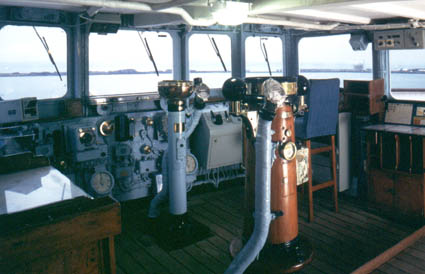
Bridges
It will been seen from the profile that the bridge front is terraced to provide deck space at shelter deck level for an Admiral’s bridge and at bridge deck level for a Royal bridge. These are design requirements but the problem of wind protection on these bridges is in consequence much more difficult to solve than with the conventional cliff front.
In particular it was necessary to provide the maximum wind protection on the Royal bridge. The configuration of structure, particularly the forecastle sunk between high bulwarks and the open deck at shelter deck level, leads to a strong back draught on this bridge.
To obtain a good view forward from the Royal chart house the height of bulwarks on the Royal bridge was limited to 3 ft. 10 in. On these bulwarks are fitted specially designed portable glass screens, 1 ft. 9 in. high, which can be quickly hinged down and stowed neatly against the bulwark when not in use.
Wind tunnel experiments at the N.P.L. Teddington on a large scale model of the bridges showed that the bulwarks and screens alone were insufficient to prevent the wind striking the structure at the back of the bridge and descending in strong eddies on to the deck of the Royal bridge. Consideration was then given to fitting a wind alley to trap the descending air and guide it to the sides of the ship. Experiments were conducted to find the optimum position of such a screen and it was finally fitted 3 ft. 6 in. from the superstructure (though this position was not found to be critical) and with a height of 3 ft. 10 in. Also, extensions at each side, of full height between decks, were fitted to the front of the Royal chart house to protect the entrances to the chart house from the high wind velocities in the wind alley.
There are considerable improvements effected by the wind alley and side screens in a typical case with the wind 10 deg. off the bow. The traverses are taken at heights of 2 ft. 3 in. and 6 ft. above the deck and the velocities in the table are expressed in terms of percentage and free stream velocity.
Accommodation
Accommodation for the Royal party and staff is aft and for the ship’s company forward.
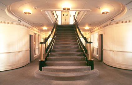
The Royal apartments are on the shelter deck between the main and mizzen masts with a veranda at the after end leading on to a sun deck. A point which may be noticed from the profile is that the deck of these apartments is 2 ft. higher than the general shelter deck level so that the external fore and aft gangways are well below the windows of the Royal apartments.
The main staircase from the Royal apartments on the shelter deck leads to a vestibule on the upper deck about which are grouped the State apartments. At either side of the vestibule are Her Majesty’s and His Royal Highness’s sitting rooms. The dining-room, drawing-room and ante-room extend the full width of the super-structure without obstruction from pillars. Sliding screens are fitted at the entrance to the ante-room and between the ante-room and the drawing-room. They can be folded back when required to provide a large reception space from the after end of the drawing-room to the foot of the main staircase.
The main staircase continues down from the upper deck to the main deck, in the vicinity of the main entrance ports. The Household and guest cabins, sitting-rooms and cloak rooms are on this deck. These rooms are fitted out to first class passenger liner standards.
The Royal staff is accommodated on the lower deck, the rooms being fitted out to Service standards.
A passenger lift is fitted near the main staircase and operates between the main and shelter decks.
The crew of 21 officers and 250 men is accommodated forward in a manner generally in accordance with Service practice except than the C.P.O.’s occupy 4-berth cabins.
The suitability of the decorative design and the furnishing of the Royal and State apartments has, of course, been very important. Her Majesty and His Royal Highness The Duke of Edinburgh have both taken a great interest in the work and have personally approved the decorative treatment of the walls and ceilings and the design of new furniture and have chosen the soft furnishings.
In the interests of economy, use has been made as far as possible of furniture from the Victoria and Albert and of new pieces supplied for use in s.s.Gothic for the Commonwealth tour.
Messrs. John Brown appointed Messrs. A. McInnes Gardner & Partners as their decorative architects for this work. Because of its importance from the standpoint of current British decorative art it was considered desirable to have the advice of a second specialist in this field and Sir Hugh Casson was appointed as consultant to the Admiralty. The result of this collaboration has been very successful.
Details of the decorative schemes and furnishings have not been included in this paper as it has been decided that this information cannot be released until Her Majesty has personally seen the Royal and State apartments.
Layout as Hospital Ship
In the initial stages of the design the Medical Director General of the Navy was consulted about the requirements for the vessel in her role as a hospital ship. It was thus possible to proceed with the designs for a hospital ship and a Royal Yacht concurrently, so that the conversion could be made in the most economical manner. In consequence, relatively little alteration to existing structure and equipment will be required in the unhappy event of war making the conversion necessary.
The wards, which will accommodate 200 patients, will be located in the after part of the ship. Most of the patients will be medical and surgical cases requiring normal hospital conditions, but provision has also been necessary for zymotic cases and those suffering from tuberculosis. Zymotics will be accommodated in glazed cubicles built within the drawing room, and these cubicles together with toilet and sanitary facilities will be isolated from the remainder of the hospital. Tuberculosis cases requiring ‘fresh-air’ beds will be accommodated on part of the veranda, whilst others suffering from this disease will be berthed in wards in the space now occupied by the Royal bedrooms. The remaining wards, including the cabins and ward room for sick officers and cabins for a few female patients will be sited in the other Royal apartments and in spaces now allocated to members of the Royal Household and Staff.
Particular care has been taken in the layout of bathrooms and sanitary facilities to ensure that as little alteration as possible will be necessary in these respects upon conversion.
The operating theatre, with its annexes and its adjacent steriliser and anaesthetic rooms, will be on the lower deck, where there will also be the other specialist facilities which include an ophthalmic room, a physiotherapy room, a pathological laboratory and an X-ray room with adjacent dark room. Full facilities for dental treatment including a laboratory, will be located on the main deck.
For the care and treatment of the patients, the naval medical complement will comprise 8 medical and dental officers, 5 nursing sisters, and 47 male ratings, for all of whom existing accommodation can be readily adapted.
The ship will be manned by a merchant navy crew accommodated forward in two and four berth cabins in accordance with usual merchant ship practice. Some partitioning of the present mess decks will be necessary for this purpose.
Galleys, Cold and Cool Rooms, etc
Separate galleys are provided for the Royal party, the ship’s officers and the ship’s company, all grouped amid-ships on the upper deck. The exhaust ventilation trunks from these spaces are led up inside the funnel.
Ranges, grills and ovens are all electric, steam being supplied only for steam cookers and boiling coppers. The usual ancillary equipment is installed.
The Royal galley provides service for the Royal dining-room and also for the Royal staff messes, the food for the latter being conveyed by lift to the lower deck. This galley is of such a size and is so equipped that for hospital ship service it can provide suitable food for all the patients, although a little additional equipment will be required to cater for any Asiatics who might be embarked.
Lifts from the crew’s galley take food direct to the main lower decks for distribution to the various crew’s messes. The enclosed messes on the main deck are provided with pantries fitted with hot cupboards and automatic refrigerators. Food for the lower deck broadside messes is distributed from a large servery on the lower deck, this servery also being equipped with adequate hot cupboard and automatic refrigerator capacity.
Four main cold and cool rooms are provided for the storage of provisions. The two cold rooms (10 deg. F.) for meat and fish, one for the Royal party and the other for the ship’s company, are large enough to provide supplies for 45 days for the ship’s company, and considerably longer for the Royal party. The dairy room (32 deg. F.) and the fruit and vegetable room (35 deg. F.) are of sufficient capacity to meet the total requirements of the ship for 30 days.
An ice-making cabinet in the cooling machinery compartment makes 500 lb. of ice per day, and incorporates storage capacity for 1,000 lb.
The cooling machinery for the cold and cool rooms and for ice-making consists of two electrically-driven, water-cooled, cooling plants using Freon 12/Arcton 6 as the refrigerant, each machine being fitted with independent control valves.
The cold and cool rooms, as in modern naval practice, are refrigerated by air recirculation. Normal brine arrangements are provided for the ice-tank.

Air-Conditioning, Ventilation and Heating
An air-conditioning system serves the after accommodation spaces which in the hospital ship role will be the hospital section of the ship. This system has been designed to maintain an inside condition of 85 deg. F. dry bulb and 71 deg F. wet bulb when the outside atmospheric condition is 88 deg. F. dry bulb and 80 deg. F. wet bulb. Under cold weather conditions the installation will maintain an inside temperature of 70 deg. F. when the outside temperature is 30 deg. F.
The refrigerating machinery for air-conditioning comprises two steam get vacuum type plants each capable of extracting 1,000,000 B.T.U.s per hour under tropical conditions. The cooling medium is chilled water circulated to thirteen air-conditioning units each of which serves a particular section of the ship. The heating medium is warm water circulated to the units through heating calorifiers. Automatic temperature and humidity controllers are provided for each section.
Special attention has been paid to the ventilation installation and care has been taken to keep noise levels to a minimum. Fans and units have been grouped in acoustically lined chambers and where necessary trunking has also been acoustically lined. The low speed commercial type fans which have been adopted assist in reducing air noises and the fans themselves have been mounted on resilient mounts.
No recirculation of conditioned air is used in the system, fresh filtered air being supplied whether cooling, heating, or mechanical ventilation is in operation.
The forward accommodation spaces for the ship’s company are ventilated by fan supply and exhaust; they are heated by Admiralty pattern gilled tube type heaters in the fan supply capable of maintaining an inside temperature of 70 deg. F. when the outside temperature is 30 deg. F. These systems are manually controlled only, temperature being regulated by means of by-pass valves in the heater units. Galleys, bathrooms, workshops, etc., are ventilated with air at atmospheric temperature by fan supply and exhaust.
A separate small refrigerating unit is fitted to air condition the wireless offices.
Every effort has been made to ensure that the ventilation system is fitted with the least possible detriment to the watertight integrity of the ship. All ventilation trunking is arranged so that no main sub-division bulkhead is pierced below the main deck. To preserve the watertightness of the platform deck the ventilation trunking from hold compartments is watertight between the platform and lower decks except when the trunking leads to a fan on the platform deck. In such cases a water-tight slide valve is fitted to the trunking at platform deck level .
Above the main deck the fire division bulkheads are fitted with valves each side where pierced by ventilation trunking. Watertight slide valves are also fitted to trunking piercing the foremost and aftermost sub-division bulkheads.
The large inlets to supply fan spaces in the sides of the upper deck superstructure are provided with portable covers which can be fitted in an emergency.
Pumping, Water and Oil Services
Fire and Salvage System
Britannia has a large pumping capacity which fully meets Ministry of Transport requirements for pumping and fire-fighting.
Three 70-ton/hour motor-driven bilge pumps are fitted, one in each of the three main machinery spaces, also one 70-ton pump is fitted aft of the machinery spaces and one 20-ton pump forward. The 70-ton pump in the boiler room is an emergency submersible pump with controls geared to above the main deck. Each pump can take suction from the sea, from the compartment in which it is situated, or from the main suction line. Discharge is overboard or to the fire main. The main suction line runs throughout the ship, being well above the keel out-side the machinery spaces. Suctions are provided in all the principal compartments below the platform deck.
The fire main runs throughout the length of the ship with adequate hose connections for fire-fighting within the ship and on the weather decks. Foam arrangements are provided for fire-fighting in the machinery spaces. An automatic sprinkler system is fitted throughout the after accommodation. This system is powered by a separate sprinkler pump and can be cross-connected to the fire main should the sprinkler pump break down.
Sanitary services are supplied from the fire main through reducing valves. As a safeguard against loss of pressure in the fire main a separate sanitary pump is fitted in the system aft.
Fresh Water Systems
Allowance has been made for a higher rate of consumption of fresh water for domestic purposes than is usual in H.M. ships. Tank stowage for 195 tons of fresh water is provided, and there are two evaporators with a total distilling capacity of 120 tons per 20-hour day. A 20-ton/day feed-water distilling plant is fitted in the engine-room to provide make-up feed-water.
Fresh water storage tanks are fitted at each end of the ship. Two separate fresh water pressure supply systems are provided, one forward and one aft, and can be interconnected if required. Two 10-ton/hour pumps supply the after system and one 10-ton pump the forward system. The water is chemically treated by the injection of chlorine in to the filling main. The water is pumped from the storage tanks through fine mesh filters to the pressure tanks and then to the fresh water main through carbon dechlorinators. A small quantity of lime is added to the water in the storage tanks to make it slightly alkaline and so protect the copper piping of the systems.
Separate hot fresh water systems are also fitted forward and aft with provision for inter-connecting. Each system is heated by a 300-gallon steam calorifier with a heating capacity of 3,000 gallons per hour.
A 1-hp circulating pump is fitted in each system.
Fuel Oil System
Capacity is provided for 490 tons of fuel oil and 20 tons of diesel oil. As will be seen from the general arrangement drawings, the tanks are situated mainly in the double bottom, although deep tanks are located fore and aft of the machinery spaces. Settling tanks are provided, port and starboard, in the boiler room.
Filling connections are fitted amidships and forward, and fuel may be embarked either side of the ship. The forward position will be used mainly for replenishment at sea, for which a standard naval light jackstay rig is provided. It is expected to achieve a fuelling rate of 250 tons/hour at sea.
An oil fuel suction main runs the full length of the oil fuel tanks with branches to each tank. The oil fuel filling line is connected to this suction main in the boiler-room and the tanks are filled through the suctions. To prevent undue pressure coming on to the filling line a relief valve is fitted with discharge to the settling tanks. Oil can be transferred from the forward to the after tanks and vice versa, should it be require to transfer oil to correct heel or for any other purpose. It cannot, however, be transferred from the port to starboard tanks in the same group.
To avoid the objectionable oil fuel odours associated with individual air escapes led to the weather deck, it was decided to adopt the practice, now current in large passenger ships, of joining all fuel tank air escapes to a common line vented by a large bore pipe led inside the funnel. The precautions usually adopted with this system, including the provision of spill tanks, have been taken.

Sewage System
Careful consideration was given during the design to the arrangements for disposal of sewage and waste water. The problem was important because of the probability that the ship, in either role, may be required to lie in restricted, perhaps non-tidal, harbours for long periods with her full complement on board.
One possibility considered was the mechanical separation of liquids and solids, and the treatment and stowage of the solids until a convenient opportunity for discharging occurred. Another line investigated was the use of a comminator to break up solids and produce a fine sludge which could be discharged overboard. Unfortunately, both these ideas had to be abandoned in favour of the more conventional arrangements already in use in merchant ships since, so far as is known, neither system had been tried before in ships and shortage of time precluded satisfactory development.
Two entirely separate sewage and waste water systems are fitted, one forward and one aft. This will enable the system aft to be completely shut down when it is not required. Each system discharges to a sewage tank which is pumped out by either of two pumps operated by float control. Two overboard discharges are provided, one each side the ship for each system and either pump may discharge either side. The sewage tank may be by-passed if necesary.
The size of the sewage tanks which could be fitted was limited by the space available. In order to reduce the frequency of pumping out the tanks when necessary, arrangements have been made for the disposal of waste water from baths, etc., directly over board in harbour, if desired.
Equipment - Anchors and Cables
The anchor and cable equipment consists of:
3 60-cwt. Admiralty pattern stockless bower anchors (one spare).
270 fathoms of 1 7/8 in. forged steel stud link cable.
1 20-cwt. Admiralty pattern stockless cast head type stream anchor.
1 300-lb. Danforth kedge anchor.
Recessed stowages are provided for the bower anchors, port and starboard, and considerable care was taken to get a good working arrangement consistent with keeping the size of the anchor recesses to a minimum. A 1 in. scale model and later a full scale mock-up were produced to ensure the development of satisfactory hawse pipes and recessed stowages.
A twin-headed electrically driven capstan and cable gear is fitted forward driven by a 64 h.p. motor slung beneath the fo’csle deck. The cable holders are suitable for working 1 7/8 in. steel cables and the barrels are suitable for 4 ¾ in wires. The capstan is capable of exerting a pull on either cable, but not simultaneously, of 20 tons at 25 ft./min. and hoisting slack cable equivalent to a pull of 1 ½ tons at 40 ft./min. The gear is capable of exerting a pull greater than 48 tons but the clutches are designed to slip at a load of 50 tons. A warping pull of 15 tons at 33 ft./min is possible from either capstan barrel and the brake gear is capable of holding 30 tons without creeping.
No arrangements are fitted for catting the anchors; special fairleads are fitted at the bow port and starboard for use when securing to a buoy or when being towed.
An electrically-driven capstan is fitted aft for working 4 ¾ in. steel wire hawsers; it can exert a pull of 5 tons at 25 ft./min. and heave in slack at 40 ft./min.
Boats and Life-saving Equipment
The boat complement is large by Service standards for the size of ship, and consists of:
1 40-ft. Royal barge.
2 35-ft. medium speed motor boats.
1 32-ft. motor cutter.
2 27-ft. jolly boats (sea boats).
2 16-ft. fast motor dinghies.
2 14-ft. sailing dinghies.
These are all service boats, although the 35-ft. and 27-ft. boats are recent designs. The 40-ft. Royal barge was originally built in 1938 for use with the Victoria and Albert. It is a hard chine boat fitted with triple diesel engines and it was last used at the Naval review at Spithead in June 1953.
The 35-ft. motor boats are of round bilge form, and are not designed to achieve planing speed. The acceptance of medium speed permits the installation of robust diesel engines. The main consideration governing the hull construction has been lightness in association with maximum strength.
The 27-ft. jolly boats are to be the future sea boats in the Navy, displacing the old 27-ft. whalers. In some respects they resemble a small edition of the R.N.L.I. lifeboat. The engine has a closed circulation system which enables it to be started up with the boat in the davits, so ensuring that the engine is running properly before the boat is water-borne.
All power boats are diesel driven.
In addition to the life-saving capacity of the boats, Britannia carries 18 life rafts of a new design recently introduced into the naval service. They are of a self-inflating type, stowed on board in valises, and weigh with stores about 440 lb. each. The raft consists of an oval-shaped float with centre thwart and floor and an arched canopy, all of which are inflated by CO2 under pressure. Each raft comfortably holds 20 persons. The raft in its valise is thrown overboard secured to the ship by static line. If the line is pulled the raft inflates, automatically breaking the lacing of the valise. Trials have shown that the rafts inflate the right way up irrespective of how they enter the water.
The six larger powerboats are stowed in overhead type gravity davits. Single part falls are provided for the rapid lowering of the seaboats, the other boars using two part falls. The 40-ft. and 35-ft. boat davits are fitted for power hoisting and lowering and emergency gravity lowering and the 32-ft. and 27-ft. boat davits for power hoisting and gravity lowering. A special reeling device has been designed by the davit manufacturers to ensure that the fall slower easily under no load conditions without the need for over-hauling. The device consists essentially of driving the wire mechanically over the pulleys at each davit head. For appearance the davits can be hoisted in-board when the boats are away and by this reeling device the falls can be lowered quickly when boats have to be hosted. The 16-ft. and 14-ft. boats are stowed on the shelter deck amidships and are lowered from the gravity davits, using spreaders, after the other boats are away.

Derricks and Hoisting Gear
Two large derricks are provided amidships, heeling one each side at the base of the funnel. To preserve appearances, derrick posts or cranes were considered undesirable, and a scheme has been devised whereby the funnel has been used as a derrick post. Topping lifts are taken to eye plates which hinge back inside the funnel when not in use, when portable cover plates preserve the outward funnel shape. The additional time taken to rig these derricks has been accepted for the sake of appearance.
Power lifting and topping is provided by two winches, each with working load of two tons. The derricks may be used for storing ship, or as an alternative method of lifting out the motor and sailing dinghies, or for the removal of boat engines from boats in the water or in their davits. Spare motor-boat engines are carried on board in a motor-boat engine workshop so that if necessary engines may be changed at sea with the boats in the davits.
At the after end of the forecastle portable storing davits are fitted, port and starboard, having a working load of 7-cwt., power being provided, if reqiured, from the capstan.
A space for a motor car is provided on the shelter deck abreast the 40-ft. barge. The car is carried on a transporter running on an athwart-ships trackway sunk into the wood deck and terminating under the 40-ft. barge davits. The transporter and car are hoisted outboard on these davits after being raised to the davit head by wires from an hydraulic ram incorporated in the transporter.
Stabilisers
Denny-Brown single fin stabilisers are fitted in a hold compartment immediately forward of the main machinery spaces. The specification for the gear called for power to stabilise a roll of 20 deg. out to out reducing it to 6 deg. out to out at ship speed of 17 knots. The fins, which are retractable, are 4 ft. 6 in. wide, with outreach from the hull of 9 ft. 4 in. and area of 42sq. ft. each. They are capable of operating at the hull ship speed of 22 knots at the maximum fin angle which is 20 deg.
The fins are run out, rotated and retracted by an electro-hydraulic system which is capable of being controlled from the bridge. The main controlling motor is a 37 ½ bhp unit and the servo-motor a 10 bhp unit.
Laundry
The laundry has been designed to meet the requirements of the ship either as a Royal Yacht or as a hospital ship. Separate facilities are provided within the laundry to meet the requirements of the Royal party.
The output of the laundry working a 48-hour week is such that provision is made for all requirements for the Royal Family, Guests and Household and for 20 lb. of work per man per week from the ship’s company and Royal staff.
The laundry machinery is of the type normally installed in laundries of H.M. ships, except that in this case, a more generous allowance of finishing equipment is provided to meet the higher standard of appearance, which is necessary.
The steam consumption will be about 1100-lb./hr., the electrical load 18 kW and the estimated water consumption 3 tons/day.
Cinema Arrangements
The dining-room will be used for showing films to the Royal party. Projection will be from the servery through ports in the forward bulkhead of the dining-room to a screen at the after end. The two 35-mm. projectors are being made so that they can be readily broken down into easily handled parts and stowed out of the way. Only 35-mm. safety base type film will be show. The projectors are capable of being adapted for 3D films.
Arrangements are made for 16-mm. films to be shown on the sun deck, in the Royal staff mess and at various positions forward for the ship’s company.
Navigation and Communications
For navigational purposes the vessel is equipped with an Admiralty (Sperry type) gyro compass installation. The master gyro is situated on the platform deck under the bridge with repeaters to the Royal chart house, compass platform, wheelhouse, bridge wings, steering compartment and emergency conning position.
An ornamental binnacle, originally from the Royal George, has been taken from the Victoria and Albert, fitted with a gyro repeater and mounted on the sun deck aft.
Magnetic compasses and associated equipment to Admiralty standards are fitted on the compass platform, in the wheelhouse and at the emergency conning position.
The wheel from the racing Yacht Britannia is used in the wheelhouse and has been suitably inscribed.
In addition, the following navigational aids are installed:-
(a) M/F Direction Finder for general use.
(b) Decca Navigator.
(c) Loran
(d) Navigational Radar Type 974.
(e) Commercial type electric log
(f) Echo sounder.
Britannia is exceedingly well equipped with radio. Four transmitting sets and their associated receivers are provided for M.F.-H.F. transmission and reception. One set is provided with its own battery equipment for emergency use if all other power supplies, including emergency generator, fail. The transmitters are designed to transmit in key or speech. A link is provided for ship-to-shore telephone communication and on certain phones speech can be scrambled for security purposes if required.
With the number of sets to be operated, whip aerials have to be used in addition to roof aerials. The whips are situated on the bridge and on the sides of the funnel.
It might be mentioned that as a matter of expediency the decorative caps on the tops of the masts are aerials.
For the conduct of State business on board, cryptographic equipment is fitted in the cypher office. Facsimile transmission is also installed. Sound reproduction equipment is fitted throughout the ship with the choice of three programmes.
Saluting Guns
It is a traditional practice to fire a morning and evening gun when Her Majesty is on board her Yacht with her Standard flying, and for this purpose two 3-pdr, saluting guns are carried on the compass platform.
Main and Auxiliary Machinery
Because of urgency, the choice of main machinery was limited to the selection of a modern well-proven unit which could be produced in a reasonably short time. It was important for both the Royal Yacht and hospital ship roles that noise and vibration should be kept to the absolute minimum and this ruled out diesel machinery which was otherwise attractive from the point of view of endurance.
A set of geared turbine machinery of power similar to that required for the Royal Yacht had been designed by Messrs. John Brown & Co. Ltd., with the co-operation of the Parsons & Marine Engineering Research and Development Association (Pamatrada), and fitted in the cross channel steamers Arnhem and Amsterdam. This set of machinery was taken as the basis for the machinery designed for Britannia. Geared steam turbines were accepted as being the most suitable although consideration was given to turbo-electric propulsion. There was no doubt that the latter would have been suitable although at some sacrifice in endurance, but its adoption was not possible because of the large amount of design work involved in the limited time available.
The machinery was developed from this basic design taking into account the following requirements:-
the machinery to be capable of running at full power in both tropical and arctic climates,
|
good habitability in the machinery spaces, in particular under tropical conditions,
|
arrangements to meet normal Service standards for steaming under gas attack conditions to be incorporated as far as possible in the time available, except where such arrangements would prejudice the function of the ship as a Royal Yacht. To enable the ship to be steamed under such conditions boiler combustion air has been trunked direct to the boilers. Separate ventilation has been fitted to the open boiler-room which would be closed under gas attack,
|
special precautions to be taken as far as possible against shock damage from underwater explosions. Although full shock requirements to naval practice have not been insisted upon, cast iron has been eliminated from all main and auxiliary machinery,
|
the machinery to be as smooth and silent running as possible and all avoidable vibration eliminated at its source. Resilient mountings have been fitted beneath the diesel generator to reduce structural-borne vibration.
|
The main boilers are so arranged that either boiler can steam both the port and starboard engines, a suitable cross-connection valve in the engine-room facilitating this arrangement. The electrical generating sets with their auxiliaries are situated in a separate generator room at the forward end of the machinery spaces as far from the State apartments as practicable.
The main machinery in Britannia consists of two sets of turbines and gearing, each set comprising one H.P. turbine and one L.P. turbine in which is incorporated the astern turbine, all constructed by Messrs. John Brown & Co. (Clydebank) Ltd. Single reduction hobbed and shaved gearing is fitted, driving the shafts at 285rpm when the maximum power of 6,000 shp per shaft is being developed. Full power revolutions of the H.P. and L.P. turbines are 4,910 and 3,550 rpm respectively. The condensers, which are of the two-flow type, are under-slung beneath the L.P. turbines and are supplied with circulating water by electrically driven pumps with a maximum capacity of 10,000 gall./min. for each condenser. A conventional close-feed system is fitted using an auxiliary condenser in the boiler-room for harbour steaming conditions.
Steam is generated from two main boilers, each having a capacity of 75,000-lb./hr. at a pressure of 300-lb./in.2 and a temperature at the superheater outlet of 660 deg. F.
The boiler combustion air is trunked to the boilers and is drawn by electrically driven forced draught fans from a plenum space at the base of the funnel into which the exhaust ventilation from the boiler-room is discharged. Thus, warm ventilation exhaust from the boiler-room is fed to the boilers augmented by fresh air from the atmosphere drawn through slats in the plenum space.
The exhaust gases from the boilers are extracted by electrically driven induced draught fans and discharged through grit arresters to the atmosphere. At full power the gases leave the funnel with a velocity of about 110-ft./sec. and a temperature of 400 deg. F.
It is essential for the efficient operation of the grit arresters and to keep the funnel discharge well clear of the ship, that a high efflux velocity of the exhaust gases be maintained under varying power conditions. This is obtained by hydraulic control from the boiler-room platform of the inlet flaps to the grit arresters, which allows the number of arresters in use to be adjusted to suit the power.
An auxiliary boiler is installed to meet harbour requirements. It has an evaporating capacity of 20,000 lb./hr. at the same steam conditions as the main boilers, and can be used to augment the main steam supply.
The main and auxiliary boiler feed pumps and the main engine auxiliaries are electrically driven. Two salt water evaporating and distilling plants, each having an output of 60 tons per day, are fitted in the generator room and a 20 ton per day feed water evaporator is sited in the engine-room for make-up feed purposes.
The ventilation and general conditions in the machinery spaces during trials were most satisfactory and well repaid the close attention given to these matters during the design stage. The engine-room is ventilated by two axial flow and two centrifugal supply fans with a total output of 30,000 cu. ft./min. and three axial flow exhaust fans with a total exhaust of 32,000 cu. ft./min. The slight negative pressure in the engine-room should prevent warm air escaping into the ship through the engine-room entrances should they be open.
The boiler-room is supplied by two axial flow fans of 10,000 cu. ft./min. each, whilst the generator room has a fan supply and exhaust of 15,000 cu. ft./min.
Steering Gear
The steering gear is of the electro-hydraulic type with two separate motor-driven variable delivery pumps either of which is capable of actuating the rudder under maximum torque conditions. The pumps are telemotor controlled from the wheelhouse and by mechanical control in the steering gear compartment. A separate hand operated variable delivery pump is available for emergency operation of the gear.
Funnel
The size and shape of the funnel were finally decided with the assistance of the Aerodynamics Division N.P.L., who conducted wind tunnel tests of various funnel designs for the Admiralty.It was desired that the funnel should have a pleasing appearance, that the decks should be free from smoke and funnel gases, and that the funnel paint-work should not be discoloured by smoke and gases eddying in the vicinity of the funnel top.
As was to be expected, the most efficient funnel suggested by the wind tunnel tests was unacceptable on account of height and shape of top. Whilst space does not permit of a full discussion of the tests, it is of interest to compare the design of funnel first tested (A) with that finally fitted (B).
With funnel A there was a breakdown in smooth air flow around the funnel and considerable eddying around the top edge as soon as the wind direction became slightly off the bow. The eddies of smoke extended down the side of the funnel to the superstructure level. In funnel B the width is decreased by 4 ft. and a front of better aerodynamic section substituted for the semi-circular front. Although there is still a breakdown of smooth air flow round this funnel section it occurs with the wind much further off the bow than with funnel A. The top of funnel B is cased in. This casing is streamlined in the fore and aft direction with circular sections athwartships. With these changes there was a great improvement in funnel performance. Further improvement was obtained by grouping the uptakes instead of distributing them over the funnel top. In funnel B the uptakes are actually 2 ft. higher than the funnel A although the fore end of funnel B is 1 ft. 3 in. lower than in funnel A.
A major factor in producing a clean ship is the high efflux velocity of the exhaust gases in the full and part power conditions. Effux velocities in this ship are high and vary between 110 ft./sec. with power of 12,000 shp to 80 ft./sec. at 1,000 shp. As already stated grit arresters are fitted.
It will be noted that a gutterway is fitted around the top of the funnel so that rain water can be drained away to prevent discoloration of the funnel sides.
Exhausts from the galley, laundry and lavatory fans, and from the diesel generator and incinerator are led up inside the funnel.

Electrical Installation
When considering the generator requirements it was decided that:
when the Royal party is on board or when the ship is in use as a hospital ship it would be necessary to have steam on the main boilers and the steam turbo-generators would carry the electrical load. For harbour use at other times a diesel generator would be installed to cover the harbour load,
|
the diesel generator would not be used at sea because of noise and vibration,
|
the generator capacity provided must be capable of meeting requirements with adequate standby power,
|
the emergency dynamo required by M.O.T. regulations to be regarded as a completely separate item to the above commitments.
|
The dynamo load at sea was estimated to be approximately 730 kW and the harbour diesel load bout 250 kW.
The following generators are fitted in Britannia for lighting and power supplies:
3 500 kW steam turbo-generators.
1 270 kW diesel generator.
1 60 kW emergency diesel generator.
Consideration was given to fitting an a.c. installation in accordance with recent Admiralty policy for H.M. ships, but once again, the time factor precluded the possibility of obtaining delivery of new generators in time to avoid delay in completion of the ship. Furthermore, most of the main machinery auxiliaries were planned for electrical drive; the economic operation of these auxiliaries, including boiler-room fans, depended upon the availability of a speed control range not obtainable with standard type a.c. motors.
Considerable difficulty would also have been experienced in obtaining delivery of d.c. turbo-generators in time to meet the completion date of the ship, and it was therefore fortunate that three 500 kW d.c. machines were available and not otherwise required. These machines were not compounded, however, and it was necessary for this to be done, and for further modifications to be made to meet Lloyd’s requirements before the generators could be installed in Britannia.
The d.c. installation in Britannia is at a constant voltage of 225, all permanent wiring being on the two wire, two conductor system with both poles insulated.
The three turbo-generators are fitted in the generator room and any two are capable of supplying the full sea-going load. The 270 kW diesel, also fitted in the generator room, is capable of meeting the harbour load or the salvage load when steam is not available. To allow for maintenance of this diesel generator in harbour when necessary, steam can be supplied from the auxiliary boiler to run one of the turbo-generators to cover the harbour load. The generators feed into a main switchboard in the generator room. Distribution from the main switchboard to the various circuits is by double pole circuit breaker, switches and fuses following normal practice.
The emergency diesel generator, together with its own starting battery, is situated in a shelter deck compartment to meet M.O.T. requirements. It feeds into a switchboard fitted adjacent to the generator and in an emergency will supply vital services such as radio, salvage pumps, emergency lighting and the power operated watertight doors.
A.c. services are supplied by two d.c./a.c. motor generators of output 35 kVA, 230 volts, 50 cycle, single phase. An a.c. switchboard is fitted with two control panels to distribute the power required for radio, sound reproduction equipment, X-ray, cinema and echo sounding.
Two 220/24 volt d.c./a.c. motor generators with control gear, a 24-volt secondary battery, and a switchboard are fitted in the low-power room for supplying the gyro compass equipment, log, telephones, gongs, alarm bells, etc.
A permanent system of degaussing is fitted and is fed from the 225 volt system.
The electrical installation and equipment are generally in accordance with Lloyd’s rules for electrical equipment in ships.
Following the latest service practice, fluorescent lighting has been fitted in messes, offices, workshops, galleys and bathrooms.
The lighting in the Royal and State apartments is generally by wall bracket and ceiling fittings, although in the dining-room some concealed strip lighting has been used.
Arrangements are made for flood-lighting the ship and for the customary outline illumination.
As a matter of interest Britannia is the first service ship to be fitted with electric battery feed emergency navigational lanterns instead of oil burning emergency lights.